RGB Rotary Encoder in CircuitPython for Raspberry Pico
So in my latest project I wanted to get an RGB rotary encoder for my Pico running CircuitPython. The reason for using CircuitPython is that I am creating a specific piece of hardware in which the library I cannot (or dare not) re-write. I want to make a Human Interface Device (HID) using the Raspberry Pi Pico and the only solid library I can find is the one by Adafruit. This fundamental decision means that any hardware with which I intend to interface then requires that I use libraries in CircuitPython, or C++.
Getting to know the hardware
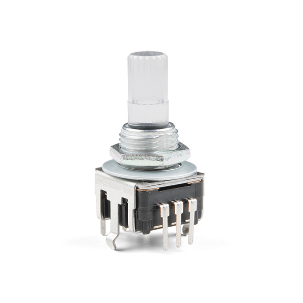
It’s really important to read the datasheet for the electronics with which you are going to be playing. While this one is not great, it at least provides clues about the hardware that allow users to know a few things. This hardware includes:
- an RGB common anode LED (page 10 of 10). Learn about the differences of RGB LED’s
- a push-button switch
- a rotary encoder (phew)
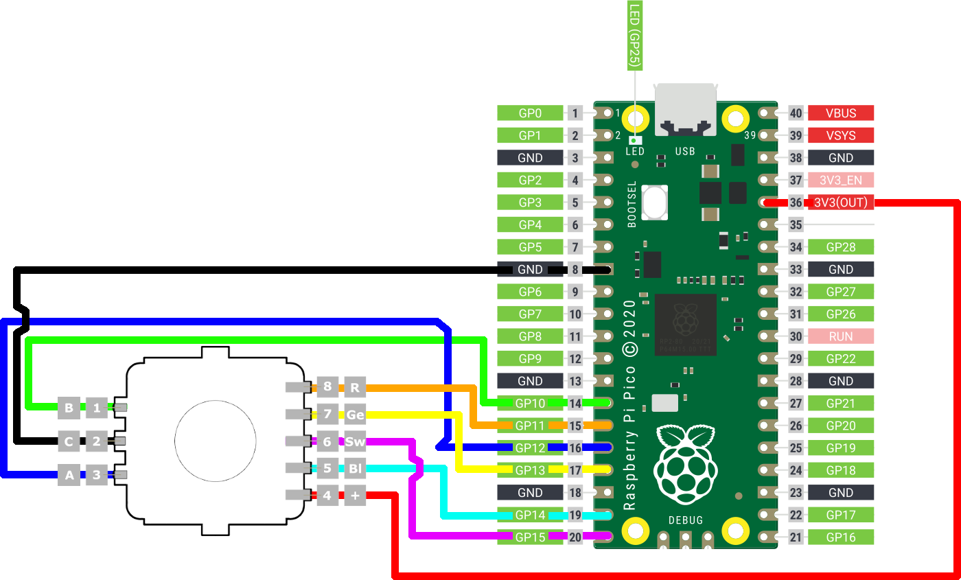
In my mind, these seemed to be the list in order from easiest to hardest… I was wrong. Having played with common cathode RGB led’s I was left utterly confused. It took me the better part of a day to figure it out. The most annoying part is an absolute lack of a pin out. While it it seemingly obvious to others, it’s not obvious to me.
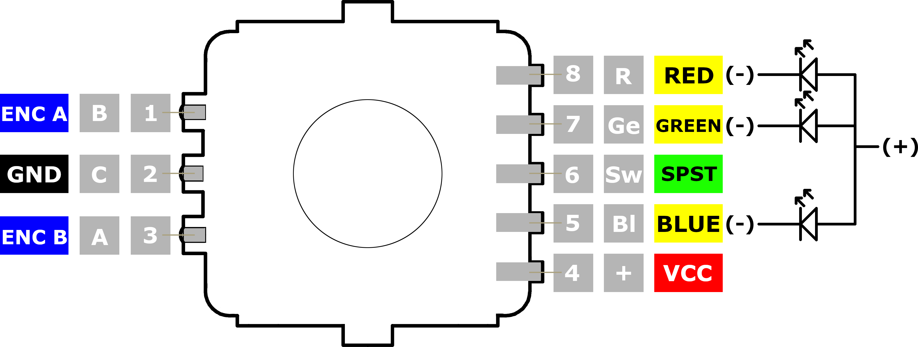
I know the wiring elements on the right are not necessarily part of a pinout diagram, however it was these elements of the data sheet that REALLY helped me understand that it was common anode as opposed common cathode. I based the pinout on the data sheet and other information I have found, like the breakout board, which allows for two types of rotary encoder.
I have separated out the components and code so that if you only need one element, you can skip ahead to that one.
Raspberry Pico CircuitPython RGB LED common anode
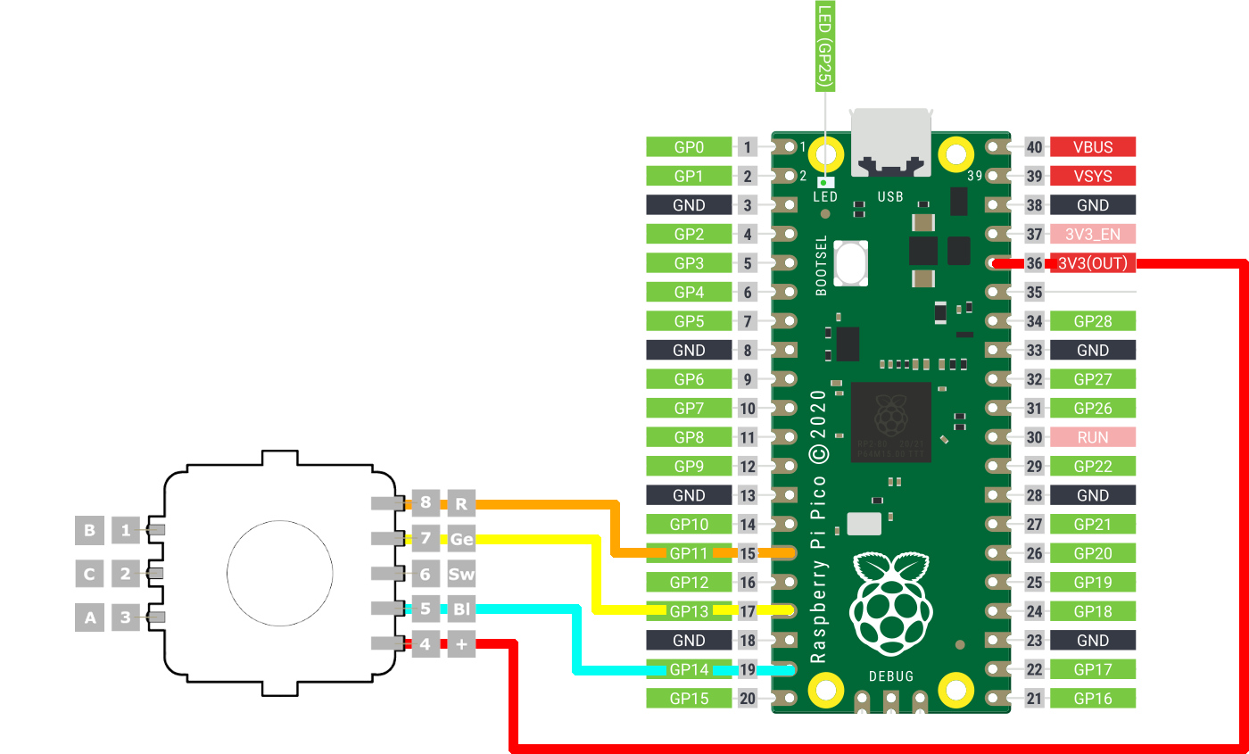
The Raspberry Pico board has three Analog to digital converters, meaning that if we are going to run dimming on the LED’s (on any other pins), then we’re going to have to use pulse width modulation (PWM). There is a reference note in the Adafruit CircuitPython Pico documentation (page 82) that if you have trouble, change the pin you’re using. I had to fiddle around a bit.
Wiring
Code
import time
import board
from pwmio import PWMOut

PWM_FREQ  = 5000
COLOUR_MAX = 65535

rPin = PWMOut(board.GP11, frequency=PWM_FREQ, duty_cycle = COLOUR_MAX)
gPin = PWMOut(board.GP13, frequency=PWM_FREQ, duty_cycle = COLOUR_MAX)
bPin = PWMOut(board.GP14, frequency=PWM_FREQ, duty_cycle = COLOUR_MAX)

# Converts a value that exists within a range to a value in another range
def convertScale(value,
                 originMin=0,
                 originMax=255,
                 destinationMin=0,
                 destinationMax=COLOUR_MAX):
    originSpan = originMax - originMin
    destinationSpan = destinationMax - destinationMin
    scaledValue = float(value - originMin) / float(originSpan)
    return destinationMin + (scaledValue * destinationSpan)

# This method ensures the value is in the range [0-255]
# it then maps the value to a number between [0-65535]
# it then inverts the value
def normalise(colourElement):
    value = colourElement
    if value > 255:
        value = 255
    if value < 0:
        value = 0
    return COLOUR_MAX - int(convertScale(value))

def setColourRGB(red, green, blue):
     rPin.duty_cycle = normalise(red)
     gPin.duty_cycle = normalise(green)
     bPin.duty_cycle = normalise(blue)

def setColour(colour, x = None, y = None):
    if x != None and y != None:
        setColourRGB(x, y, z)
    else:
        setColourRGB(
            (colour >> 16) & 255,
            (colour >> 8) & 255,
            colour & 255)

while True:
    setColour(0xff0000)
    time.sleep(0.5)
    setColour(0x00ff00)
    time.sleep(0.5)
    setColour(0x0000ff)
    time.sleep(0.5)
Raspberry Pico CircuitPython SPST Switch
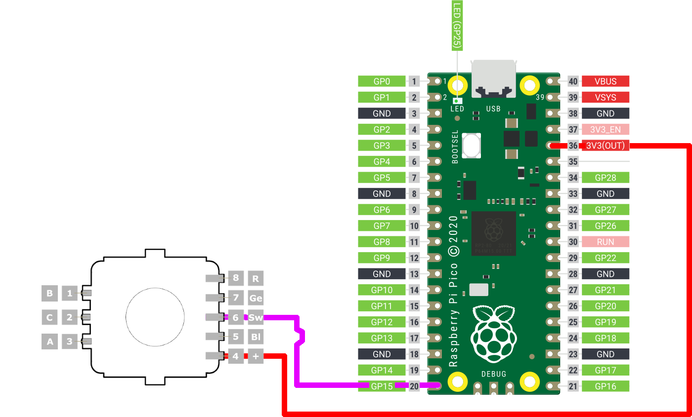
Due the RGB LED being shared anode, the switch needs to be pulled down when reading. It also requires power to be connected. A Single Pole Single Throw (SPST) switch has only one input and only one output terminal.
Wiring
Code
from digitalio import DigitalInOut, Direction, Pull

switchPin = DigitalInOut(board.GP15)
switchPin.direction = Direction.INPUT
switchPin.pull = Pull.DOWN

while True:
    if switchPin.value:
        print("DOWN")
Key event management can be a lot more complex, but a simple digital read is good enough to tell if the switch is open or closed. In a future post I’ll elaborate on my approach in my repo.
Raspberry Pico CircuitPython rotary encoder
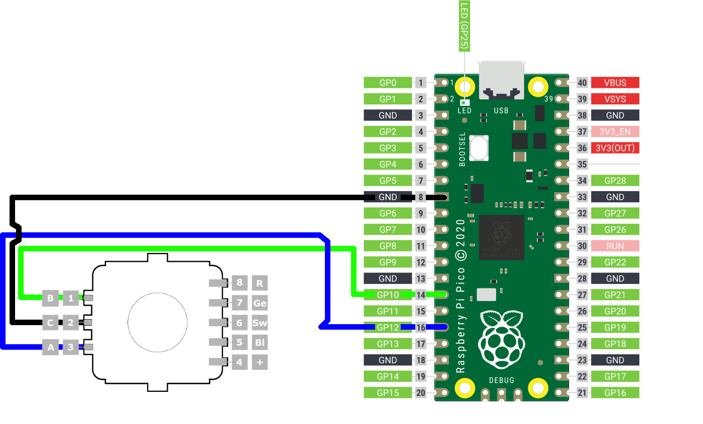
I had to roll my own since the ~rotaryio library does not work with Pico CircuitPython, presumably because either there is no pulseio library, or because of analog pin management~ (it does work now, in the 6.2.0-beta4 release). In any event, I found the “blindr tutorial” very useful in getting something to work, but converting the version at Hobbytronics much simpler
Wiring
Code
import time
import board
from digitalio import DigitalInOut, Direction, Pull

ROTARY_NO_MOTION = 0
ROTARY_CCW       = 1
ROTARY_CW        = 2

currentTime = timeInMillis()
loopTime = currentTime
encoderA_prev = 0

encoderAPin = DigitalInOut(board.GP12)
encoderAPin.direction = Direction.INPUT
encoderAPin.pull = Pull.UP

encoderBPin = DigitalInOut(board.GP10)
encoderBPin.direction = Direction.INPUT
encoderBPin.pull = Pull.UP

def timeInMillis():
    return int(time.monotonic() * 1000)

def readRotaryEncoder():
    global currentTime
    global loopTime
    global encoderA_prev
    event = ROTARY_NO_MOTION
    # get the current elapsed time
    currentTime = timeInMillis()
    if currentTime >= (loopTime + 5):
        # 5ms since last check of encoder = 200Hz
        encoderA = encoderAPin.value
        encoderB = encoderBPin.value
        if (not encoderA) and (encoderA_prev):
            # encoder A has gone from high to low
            # CW and CCW determined
            if encoderB:
                # B is low so counter-clockwise
                event = ROTARY_CW
            else:
                # encoder B is high so clockwise
                event = ROTARY_CCW
        encoderA_prev = encoderA # Store value of A for next time
        loopTime = currentTime
    return event

while True:
    original = encoderValue
    enc = readRotaryEncoder()
    if enc == ROTARY_CW:
        print("    ~~> rotary increase [clockwise]")
    elif enc == ROTARY_CCW:
        print("    ~~> rotary decrease [counter clockwise]")
Putting it all together
# ... all the previous code
# REFERENCE: https://learn.adafruit.com/adafruit-trinket-m0-circuitpython-arduino/circuitpython-internal-rgb-led
def colourWheel(pos):
    # Input a value 0 to 255 to get a color value.
    # The colours are a transition r - g - b - back to r.
    if pos < 0 or pos > 255:
        return 0, 0, 0
    if pos < 85:
        return int(255 - pos * 3), int(pos * 3), 0
    if pos < 170:
        pos -= 85
        return 0, int(255 - pos * 3), int(pos * 3)
    pos -= 170
    return int(pos * 3), 0, int(255 - (pos * 3))

  currentValue = 0
  while True:
      rotaryValue = readRotaryEncoder()
      if rotaryValue == ROTARY_CW:
          print("    ~~> rotary increase [clockwise]")
          currentValue = currentValue + 1
      elif rotaryValue == ROTARY_CCW:
          print("    ~~> rotary decrease [counter clockwise]")
          currentValue = currentValue - 1

      if currentValue > 255:
          currentValue = 0
      if currentValue < 0:
          currentValue = 255
      colour = colourWheel(currentValue)
      setColour(colour[0], colour[1], colour[2])


      if switchPin.value:
          setColour(0xffffff)
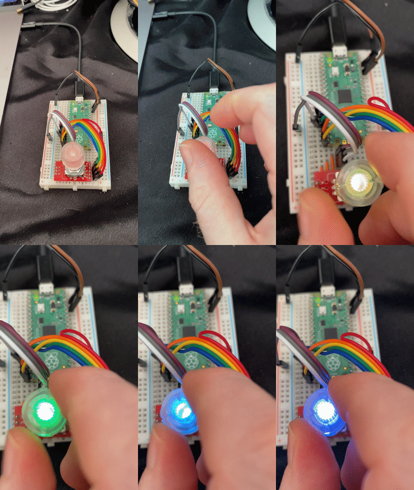
I’ll be putting these into separate classes so that the pins are variable and that it can be reused elsewhere. You can find the core project here.
Final thoughts
I am not great at figuring out the wiring of stuff, and I have not had the most pleasant experience with the specialist communities. I have found their toxic communication style only serves their ego rather than education. Please feel free to pleasantly offer criticism and corrections. I’m very eager to learn and grow. One of the things that comes to my mind is that there should probably be some resistors on the LED pins.
Comments
No comments found for this article.
Join the discussion for this article on github. Comments appear on this page instantly.